VOTER-Audio-Analysis
Introduction
This page shows the results of analyzing the audio response through an original through-hole VOTER board. As most of the background engineering on the design was lost with Jim's passing, some reverse engineering is required to dig deeper in to the design.
The data presented here analyzes the audio response between different sections of the various circuits in both the audio path, and the squelch/RSSI path.
Audio Select Lines
If you refer to the schematic, you will note that there are two Audio Select lines (ASEL1/ASEL2) connected to the 74HC4053, which determine how audio is routed through the VOTER board.
ASEL1 determines the state of the hardware CTCSS Filter. When this line is Low, the CTCSS Filter is bypassed. When this line is High, the CTCSS Filter is inserted in the audio path (default).
ASEL2 determines the state of the hardware De-emphasis Filter. When this line is Low, the de-emphasis filter is inserted in the audio path. When this line is High, the de-emphasis filter is bypassed.
On initial boot (during the bootloader phase), ASEL1 and ASEL2 are Low. With the firmware running, default options, no host connection, and no GPS, ASEL1 = H and ASEL2 = L, which means that by default the CTCSS Filter is ENABLED and the De-emphasis Filter is ENABLED.
The state of the ASEL lines can be manually overridden by the noplfilter and nodeemp options in voter.conf Documentation. They, obviously, will cause their respective filters to be disabled on the VOTER client they are configured for. NOTE: this is only true if there is a valid host connection.
In addition, Menu Item 11 (Offline De-emphasis Override) on the Offline Menu directly affects the state of ASEL2 (de-emphasis). This is true, regardless of whether Offline Mode is enabled, or not!! When Menu Item 11 is NORM, the de-emphasis filter is enabled (or at its default condition). When Menu Item 11 is set to OVERRIDE, the de-emphasis filter is bypassed.
Note however, the effect of this setting is also directly tied to the setting of Main Menu Item 13 (COR TYPE). If COR TYPE is set to NORMAL, you can toggle the de-emphasis filter with Menu Item 11 on the Offline Menu. If the COR TYPE is set to IGNORE COR, the de-emphasis filter is bypassed immediately, and Menu Item 11 on the Offline Menu has no effect.
Test Configuration
The data was captured using Room Eq Wizard software (version 5.20.5) on a Dell E6510, using the built-in sound card. The sound card response was calibrated out (calibration file created and applied).
The VOTER being used was built by VE7FET, and was running Firmware V3.00.
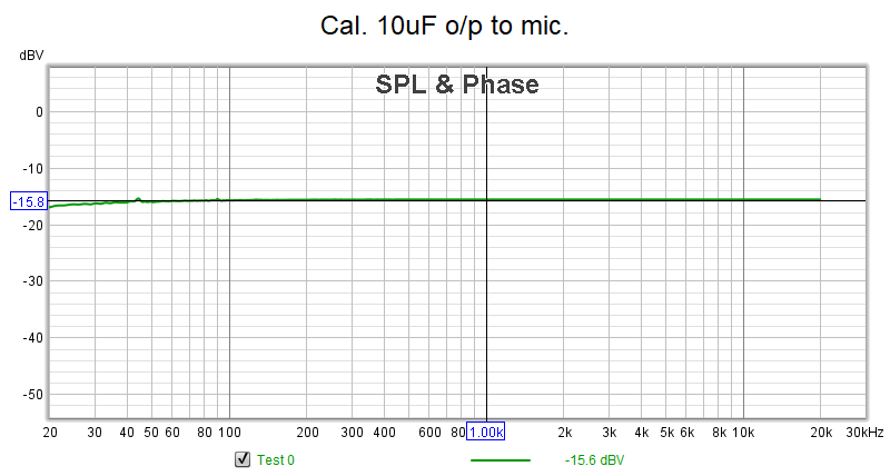
In most cases, "zero" is actually about -15.8dBm, so through measurements would be relative to that. Sorry, I didn't feel like figuring out how to reference the measurement sweeps to zero out that correction.
This is the baseline measurement, with the calibration applied, with the output of the sound card connected to the input, using a 10uF capacitor on the microphone input (DC blocking).
The sweeps presented below should be used as a general representation of the audio characteristics of the path. This is definitely not a scientific, lab-grade experiment. I was more interested in what the relative responses were of various parts of the circuit, as well as the effect and operation of various option settings in the config file (and menus).
Audio Circuitry Sweeps
Input Amplifier Response
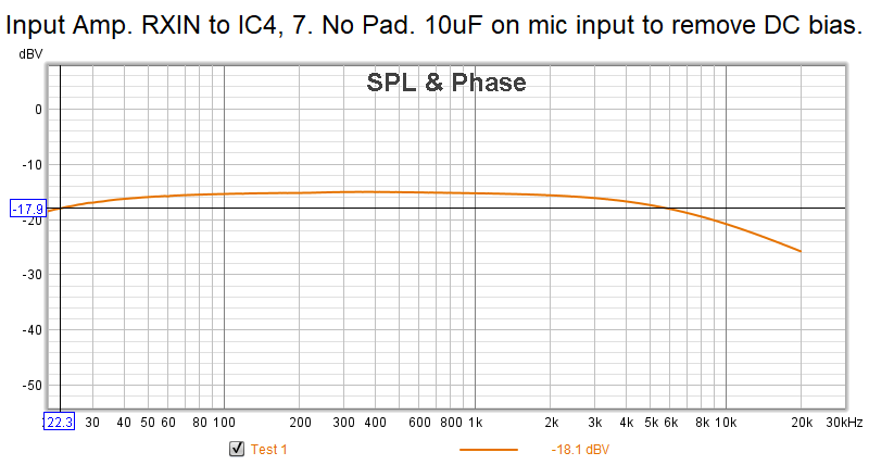
Sweeping from Radio DB9 Pin 3 to U4 Pin7. 10uF cap on Mic input of sound card. No host connection. It appears there may be some interaction with the test setup causing a slightly non-flat response (compared to when JP2 is inserted).
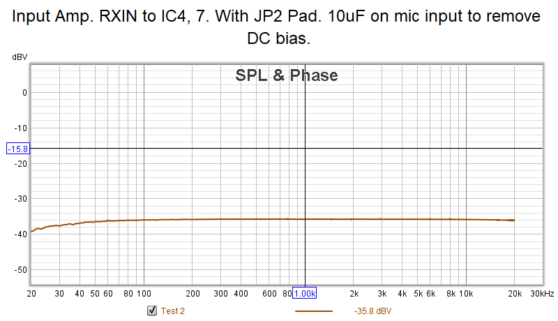
Inserting JP2 (20dB Pad):
CTCSS Filter Response
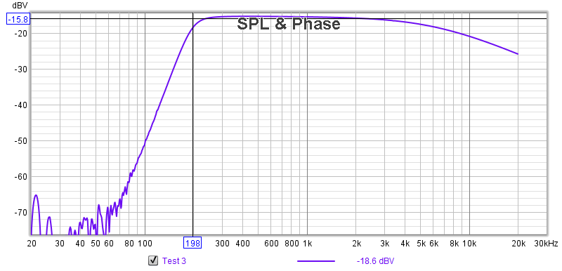
Sweeping from Radio DB9 Pin 3 to U14 Pin 1 to characterize the response of the high-pass CTCSS Filter. 10uF cap on Mic input of sound card. No host connection. JP2 is OUT.
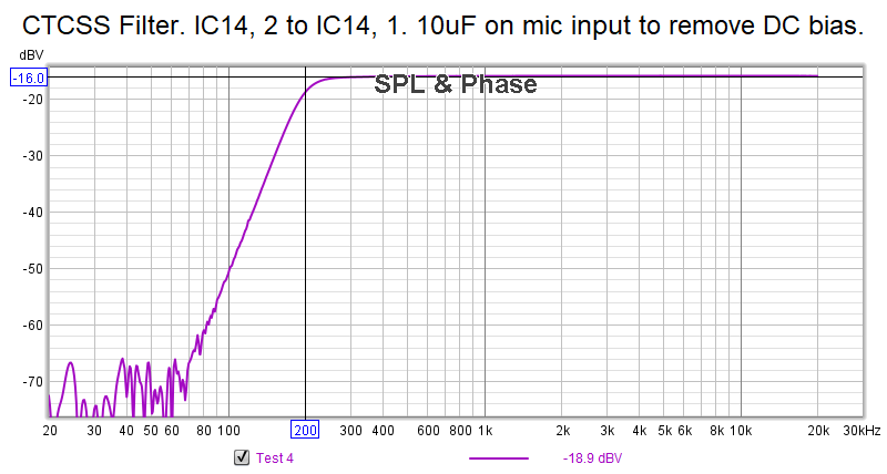
Sweeping from U14 Pin 2 to U14 Pin 1, just the CTCSS filter by itself:
Again, the interaction can be seen when sweeping through the Input Amp (a slight roll off at the higher end frequencies). Response is flat when sweeping through the CTCSS Filter directly.
The 3dB point of the filter is about 197Hz.
Anti-alias Low-pass Filter Response
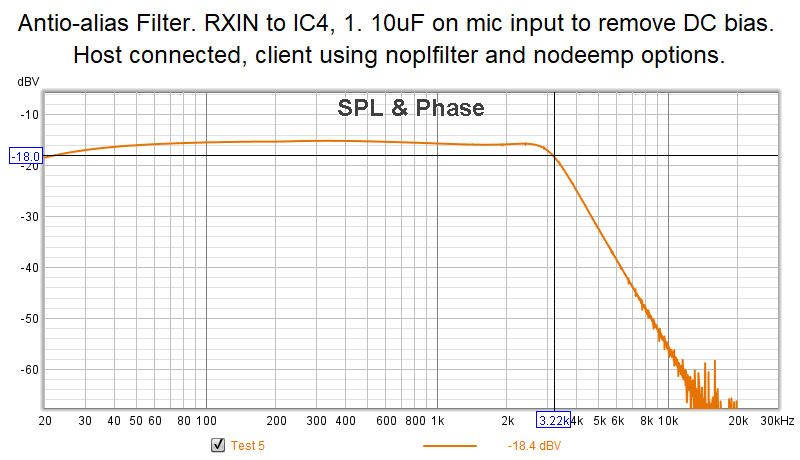
Sweeping from Radio DB9 Pin 3 to U4 Pin 1 to characterize the response of the Anti-alias LPF. 10uF cap on Mic input of sound card. Host connection established (mix mode/no GPS), nodeemp and noplfilter options set on client config to bypass hardware CTCSS and De-emphasis Filters (ASEL1=L, ASEL2=H).
The Anti-alias LPF 3db point is about 3.22kHz. Fairly flat response through the audio pass band (up to 3kHz).
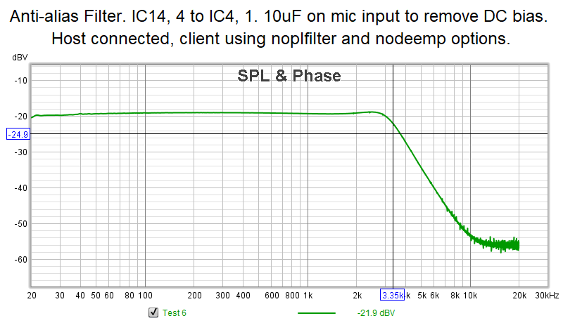
Sweeping from U14 Pin 4 to U4 Pin 1. Just the Anti-alias Filter directly:
There appears to be some impedance mismatch with the test setup, as there is higher loss observed... but the response is about the same.
