Radio Connections: Difference between revisions
imported>N8THN mNo edit summary |
imported>Wd6awp No edit summary |
||
| Line 2: | Line 2: | ||
GPS | =GPS= | ||
* [[Media:RTCM 2 Trimble.pdf|Trimble RTCM Interface Cable]] | * [[Media:RTCM 2 Trimble.pdf|Trimble RTCM Interface Cable]] | ||
* [[Media:RTCM 321 Cable.graffle.pdf|Trimble to Two RTCMs and Lady Heather Cable]] | * [[Media:RTCM 321 Cable.graffle.pdf|Trimble to Two RTCMs and Lady Heather Cable]] | ||
Revision as of 20:58, 4 November 2018
Instructions for connecting radios, repeaters and AllStarLink interfaces including the RTCM, GPS, URI/URI X and like devices.
GPS
Motorola
CDM
CDMs make great nodes. This eBay reseller has very nice cables. Use to connect to URI or RTCM.
CDM Cable from Kurt Meltzer ex-WB9KNX, now KC4NX - Cable 83 has only one output to use for either COS or CTCSS. Use another cable if you need both COS and CTCSS.
Maxtrac
The venerable Maxtrac is a radio that was very well built, apparently has very stable reference LO, and can take a beating. When aligned properly, and sufficient *vectored* cooling is made, this radio will last for a very long, time even under several hours with of transmitting per day.
The radio will need to be aligned, and programmed to the frequenc(y/ies) you want to use. You will also need to program the Accessory Option for PL/DPL & CSQ Output.
- Most URIs can accept active high or active low for valid RX signal detection, ie, open squelch. It is HIGHLY recommend in any situation COS is set to USB or active high. This will prevent issues. Too many to mention.
- It is a good idea to program pin 8 on the Maxtrac/GM300 for PL/DPL & CSQ output, active high. This will cause the radio to emit a 5Vdc signal when the squelch is open, and go low when squelch is closed.
TX/RX audio, COS, and PTT connections
With the radio facing you in normal operating positing, volume knob on top left, and mic connection right below it, turn the radio over from the right side. The accessory connector is located on the rear, right top of the radio at this point. Starting from left to right, the pins on the top are / and the pins on the bottom are /. If you want to hear audio from the radios speaker, just a header jumper on the far right pins 15 and 16.
This section is a work in progress.
References: The GM300 section has the link for further reading; the Maxtrac and GM300, are relatively close in design.
MTR-2000
Quantar
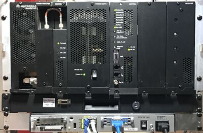
The Quantar can be tricky to interface as it's extremely programmable and you will need a wireline card for I/O connections. By default the I/O will not work unless the "wildcard" table is programed. This wildcard table is Boolean logic of interrupt states in the radio, is extremely flexible and frustrating to debug. It's a base station in it's own class.

Note you will want to use BEW mode on the RTCM if using the RTCM do squelch.
- Another Quantar/RTCM Interface Cable
- Astro-TAC/RTCM Interface Cable
- Interfacing to a Quantar with P25NX - Bryan Fields W9CR has page on interfacing the Qunatar using simple USB into Allstar and P25NX linking at the same time. This is driven by programing on the Quantar Wildcard tables.
- Quantar/URI Cable
- Quantar MRTI/URI Cable
Syntor X
The Motorola Syntor X with an Xcat installed makes a great frequency agile remote base. For more information see this Syntor Xcat page.
VRM-850
GM300
These older radios are fairly common and easily to come by due to the narrow banding. Probably the hardest part is finding a computer and the RSS to program them. The Gm300 family has many different configurations, from low band VHF, to 800 Mhz. But the easiest variant of the GM300 is ones with the 16 pin connector. All about GM300 Radios
Connections are fairly simple but can be hard to determine which is the correct one to use. This link is a good place to start.
Kenwood
TKR720/820
Connections to: PTT, COS, RX audio out and MIC audio in
TX/RX board, MIC audio input, pins 4 & 5: floating ground, must not tie to any other ground! Some installations may require a 10dB, resistor L-network consisting of a 4.7k and 470 ohm resistors. The 470 ohm resistor connection across pins four and five, the 4.7k resistor is soldered to pin 5 to which your TX audio from the URI will connect to.
The MIC audio gain, deviation, and balance adjustments are *very* sensitive!
- RA-35 without TX adj. trimmer pots: Using a service monitor with deviation metering, start low and work your way up to 3KHz deviation with 1KHz tone, generated by simpleusb-tune-menu. If enabled, *904 turns this tone on and off by command, ie, no tone time-out as in simpleusb-tune-menu.
TKR750/850
Using the Masters Communications RA-35 or RA-40 radio adapters with the TKR750/850
Repeater Controller
An example of using RTCMs to replace 420 links
Spectra Engineering
- MX800 Base station - Bryan Fields, W9CR has a complete setup guide for the MX800 Base station which includes fallback to the built in controller and an audio delay module.
Tait
Beagle Board
The Beagle Board XM project.
Lox board
The Level One eXpansion board.
URI / URI X
The URI is manufactured and sold by DMK Engineering.
RA-40 / RA-35
The RA-40 is the latest version and is sold by W3KKC. The RA-40 includes audio output level control potentiometers and much more.